BBC BASIC Colour Cycling
Colour Cycling
In the last post we looked at some simple graphics commands on the BBC Micro. Typically using the graphics commands on a BBC Micro running at actual speed would be too slow to allow complex animations to run fast enough. In this post we will examine how to use colour cycling to provide cheap animation.
We looked at how the command VDU 19 can be used to change the palette of colours.
Colour cycling is a technique where we can repeatedly change the colour palette without changing what is drawn to the screen in order to animate what is on the screen.
We will investigate how this might be used for a @bbcmicrobot animation.
When we are in the 16 colour display MODE 2, the default palette is setup so each logical colour we draw graphics with will be displayed with the physical colour that has the same value.
| Logical Colour | Physical Colour |
|---|---|
| 0 | 0 (black) |
| 1 | 1 (red) |
| 2 | 2 (green) |
| 3 | 3 (yellow) |
| 4 | 4 (blue) |
| 5 | 5 (magenta) |
| 6 | 6 (cyan) |
| 7 | 7 (white) |
| 8 | 8 (flashing black-white) |
| 9 | 9 (flashing red-cyan) |
| 10 | 10 (flashing green-magenta) |
| 11 | 11 (flashing yellow-blue) |
| 12 | 12 (flashing blue-yellow) |
| 13 | 13 (flashing magenta-green) |
| 14 | 14 (flashing cyan-red) |
| 15 | 15 (flashing white-black) |
or even:
| Logical Colour | 0 | 1 | 2 | 3 | 4 | 5 | 6 | 7 | 8 | 9 | 10 | 11 | 12 | 13 | 14 | 15 |
|---|---|---|---|---|---|---|---|---|---|---|---|---|---|---|---|---|
| Physical Colour | 0 | 1 | 2 | 3 | 4 | 5 | 6 | 7 | 8 | 9 | 10 | 11 | 12 | 13 | 14 | 15 |
Here is a simple program to print numbers from 0 to 15 inclusive. Each number is drawn with the logical colour that matches its value.
  10 MODE 2
  20 FOR C=0 TO 15
  30 COLOUR C
  40 PRINT C
  50 NEXT C
We can now experiment with changing the palette.
The number zero is printed at the top of the screen with logical colour 0 but we can’t see that as it has the same logical colour 0 that the background is cleared with.
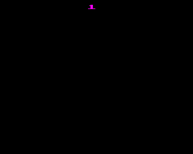
We can add some lines of code to the program above to use the VDU 19 command to change all of the logical colours to be black except for one which we will set magenta. The colour we want to set magenta is stored in the variable K. Here we will only set logical colour 1 to magenta.
   10 MODE 2
   20 FOR C=0 TO 15
   30 COLOUR C
   40 PRINT C
   50 NEXT C
   60 K=1 : REM logical colour to keep
   70 FOR L=0 TO 15 : REM for each logical colour
   80 P=0 : REM physical colour to set
   90 IF L=K THEN P=5 : REM set physical colour to magenta
  100 VDU 19,L,P,0,0,0
  110 NEXT L
| Logical Colour | 0 | 1 | 2 | 3 | 4 | 5 | 6 | 7 | 8 | 9 | 10 | 11 | 12 | 13 | 14 | 15 |
|---|---|---|---|---|---|---|---|---|---|---|---|---|---|---|---|---|
| Physical Colour | 0 | 5 | 0 | 0 | 0 | 0 | 0 | 0 | 0 | 0 | 0 | 0 | 0 | 0 | 0 | 0 |
| ^ |
Now only the number 1 appears. We have not changed what is drawn on the screen and the other numbers are still there, drawn to the screen with logical colours but they are not visible as they are all being sent to the output display using the same colour as the background.
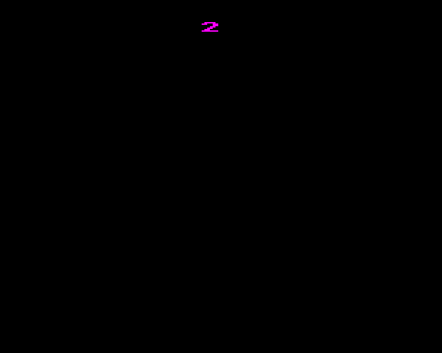
If we change line 60 to K=2, now only the number 2 appears.
| Logical Colour | 0 | 1 | 2 | 3 | 4 | 5 | 6 | 7 | 8 | 9 | 10 | 11 | 12 | 13 | 14 | 15 |
|---|---|---|---|---|---|---|---|---|---|---|---|---|---|---|---|---|
| Physical Colour | 0 | 0 | 5 | 0 | 0 | 0 | 0 | 0 | 0 | 0 | 0 | 0 | 0 | 0 | 0 | 0 |
| ^ |
We can set the whole palette in the program, then increment K and set the whole palette again and keep repeating this. When K gets too big (> 15) we can set it back to 1. This produces an animation cycle displaying each number in turn.
   10 MODE 2
   20 FOR C=0 TO 15
   30 COLOUR C
   40 PRINT C
   50 NEXT C
   60 K=1 : REM logical colour to keep
   70 FOR L=0 TO 15 : REM for each logical colour
   80 P=0 : REM physical colour to set
   90 IF L=K THEN P=5 : REM set physical colour to magenta
  100 VDU 19,L,P,0,0,0
  110 NEXT L
  120 K=K+1
  130 IF K>15 THEN K=1
  140 GOTO 70

This is the essence of colour cycling. We draw animation frames in different colours and use the palette to animate them.
Background Colour
If we go back to our original short program
  10 MODE 2
  20 FOR C=0 TO 15
  30 COLOUR C
  40 PRINT C
  50 NEXT C
And use the VDU 19 command to change logical colour 0 to physical colour 5 (magenta).
>VDU 19,0,5,0,0,0
| Logical Colour | 0 | 1 | 2 | 3 | 4 | 5 | 6 | 7 | 8 | 9 | 10 | 11 | 12 | 13 | 14 | 15 |
|---|---|---|---|---|---|---|---|---|---|---|---|---|---|---|---|---|
| Physical Colour | 5 | 1 | 2 | 3 | 4 | 5 | 6 | 7 | 8 | 9 | 10 | 11 | 12 | 13 | 14 | 15 |
| ^ |
The number zero we drew using logical colour 0 will still not appear as it is still indistinct from the background which is also filled with logical colour 0.
Using All the Colours
In the above example we could not use colour 0 in the animation as it was the ‘background’ colour. If we make an animation sequence that covers the whole screen with no real ‘background’
   10 REM Draw to the screen
   20 MODE 2
   30 D=1280/16
   40 X=0
   50 MOVE X,0
   60 MOVE X,1024
   70 FOR I=0 TO 15
   80 X=X+D
   90 GCOL 0,I
  100 PLOT 85,X,0
  110 PLOT 85,X,1024
  120 NEXT I

we could then use colour 0 in that sequence.
   10 REM Draw to the screen
   20 MODE 2
   30 D=1280/16
   40 X=0
   50 MOVE X,0
   60 MOVE X,1024
   70 FOR I=0 TO 15
   80 X=X+D
   90 GCOL 0,I
  100 PLOT 85,X,0
  110 PLOT 85,X,1024
  120 NEXT I
  130 REM Cycle the palette
  140 K=0
  150 FOR L=0 TO 15
  160 P=0
  170 IF L=K THEN P=5
  180 VDU 19,L,P,0,0,0
  190 NEXT L
  200 K=K+1
  210 IF K>15 THEN K=0 : REM We can now use 0 as part of our animation
  220 GOTO 150

Different Techniques
Different Palettes
We can get quite different effects by changing how we set the palette.
We can set the background to a different colour to the other frame colours so all the frames are always visible.
   10 MODE 2
   20 FOR C=0 TO 15
   30 COLOUR C
   40 PRINT C
   50 NEXT C
   60 K=1 : REM logical colour to keep
   70 FOR L=1 TO 15 : REM Only set 1-15, leave 0 as black
   80 P=4 : REM physical colour to set
   90 IF L=K THEN P=5 : REM set physical colour to magenta
  100 VDU 19,L,P,0,0,0
  110 NEXT L
  120 K=K+1
  130 IF K>15 THEN K=1
  140 GOTO 70
We can set more than one colour to be different to the background so that several frames are visible at once.
| Logical Colour | 0 | 1 | 2 | 3 | 4 | 5 | 6 | 7 | 8 | 9 | 10 | 11 | 12 | 13 | 14 | 15 |
|---|---|---|---|---|---|---|---|---|---|---|---|---|---|---|---|---|
| Physical Colour | 5 | 0 | 0 | 0 | 5 | 0 | 0 | 0 | 5 | 0 | 0 | 0 | 5 | 0 | 0 | 0 |
| ^ | ^ | ^ | ^ |
and we can use this to animate a sequence of colours.

We could have much more complicated logic to set which colours are active i.e. which frames to display. In fact we can arbitrarily set the animation order, which frames appear at the same time and what colour they are. Here we are randomly selecting two frames to display with a random colour.
   10 MODE 2
   20 VDU23,1,0;0;0;0;
   30 FOR C=0 TO 15
   40 COLOUR C
   50 PRINT C
   60 NEXT C
   70 LET L=RND(15)
   80 LET P=RND(8)-1
   90 VDU 19,L,P,0,0,0
  100 LET L2=RND(15)
  110 LET P2=RND(8)-1
  120 VDU 19,L2,P2,0,0,0
  130 FORD=0TO5:OSCLI("FX19"):NEXT
  140 *FX 19
  150 VDU 19,L,0,0,0,0
  160 VDU 19,L2,0,0,0,0
  170 GOTO 70
Modulo Arithmetic
The BBC BASIC instruction DIV performs integer division. If the number does not divide exactly the result is rounded down towards zero.
>PRINT 14/4
       3.5
>PRINT 14 DIV 4
         3
>_
The MOD instruction gives us the remainder after this division
>PRINT 14 MOD 4
         2
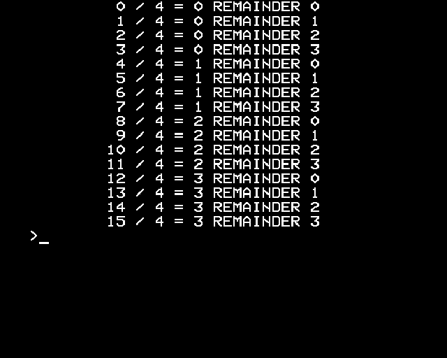
   10 MODE 7
   20 FOR X=0 TO 15
   30 M=X MOD 4
   40 PRINT X;" / 4 = ";X DIV 4;" REMAINDER ";X MOD 4
   50 NEXT X
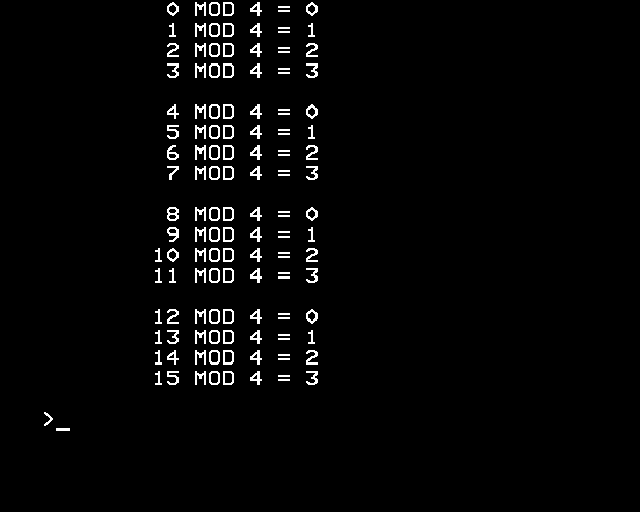
If we look at how just MOD affects number values, we see that they count up in order and then “wrap around” back to zero before they get to the value we MOD with.
e.g.
   10 MODE 7
   20 FOR X=0 TO 15
   30 M=X MOD 4
   40 PRINT X;" MOD 4 = ";M
   50 IF M=3 PRINT
   60 NEXT X
This “wrapping around” behaviour is often a very useful operation when writing a program that uses colour cycling.
For example, we can replace the update of the variable K in the colour cycling examples above.
In the case where we want K in the range 1-15
200 K=K+1
210 IF K>15 THEN K=1
becomes:
200 K=1+(K MOD 15)
In the case where we want K in the range 0-15
200 K=K+1
210 IF K>15 THEN K=0
becomes:
200 K=(K+1) MOD 16
Binary Magic
So far we have drawn individual frames so that no part of any frame is ever overlapping pixels from another frame. If we had a pixel that was in more than one frame, the technique we used so far would not work and one frame would get overwritten by another.
If we have enough colours available, there is a way we can, by reducing the number of frames we have, let us have several overlapping animation frames.
Instead of writing each animation frame as a logical colour on the screen, we can have each frame correspond to the value of a binary digit.
| Decimal Value | |||||
|---|---|---|---|---|---|
| Frame 0 in Binary | 0 | 0 | 0 | 1 | 1 |
| Frame 1 in Binary | 0 | 0 | 1 | 0 | 2 |
| Frame 2 in Binary | 0 | 1 | 0 | 0 | 4 |
| Frame 3 in Binary | 1 | 0 | 0 | 0 | 8 |
On the screen, the logical colours for a pixel are the result of OR-ing together the values for each of the frames that should be active for that pixel.
If we have a pixel that should be active on frame 0 and 2, we would store the decimal value 5.
| Decimal Value | |||||
|---|---|---|---|---|---|
| Frame 0 | 0 | 0 | 0 | 1 | 1 |
| Frame 2 | 0 | 1 | 0 | 0 | 4 |
| Colour (Frame 0 OR Frame 2) | 0 | 1 | 0 | 1 | 5 |
The drawing commands in BBC BASIC actually let us set up drawing things like this fairly simply.
The GCOL command lets us change not only the graphics colour but also how these colours are combined with what is already on the screen. One of these modes (1) is “OR” which will do a bitwise OR of the colour value already on the screen and the colour we are writing to the screen.
We can draw our 4 animation frames over the top of each other in this way.
   10 MODE 2
   20 L=1
   30 FOR F=0 TO 3 : REM Draw each frame
   40 GCOL 1,L : REM Set logical colour for the 4 frames as 1,2,4,8 with combine mode 1 (OR)
   50 L=L+L
   60 FOR B=0 TO 7 : REM Draw the 8 blades for the current frame
   70 R=RAD( B*360/8 + F*360/(8*4) ) : REM Calculate the blade angle
   80 S=SIN(R)
   90 C=COS(R)
  100 MOVE 640,512
  110 MOVE 640+S*500,512+C*500
  120 PLOT 85,640+S*250-C*100,512+C*256+S*100
  130 NEXT B
  140 NEXT F

And then we can play the animation by setting the appropriate palette. For frame 1 we turn on all the logical colours that have binary digit 0 set.
| Logical Colour | Binary Value | Enabled |
|---|---|---|
| 0 | 0000 | |
| 1 | 0001 | On |
| 2 | 0010 | |
| 3 | 0011 | On |
| 4 | 0100 | |
| 5 | 0101 | On |
| 6 | 0110 | |
| 7 | 0111 | On |
| 8 | 1000 | |
| 9 | 1001 | On |
| 10 | 1010 | |
| 11 | 1011 | On |
| 12 | 1100 | |
| 13 | 1101 | On |
| 14 | 1110 | |
| 15 | 1111 | On |
For frame 2 we turn on all the logical colours that have binary digit 1 set etc.
   10 MODE 2
   20 VDU23,1,0;0;0;0;
   30 L=1
   40 FOR F=0 TO 3 : REM Draw each frame
   50 GCOL 1,L : REM Set logical colour for the 4 frames as 1,2,4,8 with combine mode 1 (OR)
   60 L=L+L
   70 FOR B=0 TO 7 : REM Draw the 8 blades for the current frame
   80 R=RAD( B*360/8 + F*360/(8*4) ) : REM Calculate the blade angle
   90 S=SIN(R)
  100 C=COS(R)
  110 MOVE 640,512
  120 MOVE 640+S*500,512+C*500
  130 PLOT 85,640+S*250-C*100,512+C*256+S*100
  140 NEXT B
  150 NEXT F
  160 REM Cycle the palette
  170 LET B%=1 : REM Value for the binary digit for this frame (1,2,4,8)
  180 FOR L%=0 TO 15
  190 P%=4
  200 IF (L% AND B%)=0 THEN P%=0
  210 VDU 19,L%,P%,0,0,0
  220 NEXT L%
  230 B%=(B%+B%)
  240 IF B%>15 THEN B%=1
  250 *FX19
  260 *FX19
  270 *FX19
  280 GOTO 180

…
All the animated effects I have so far made for @bbcmicrobot have used colour cycling like this in order to do the animation.
The first time I tried this I got the timing wrong and didn’t start the colour cycling soon enough which turned out to be a great demonstration of how the technique works.
— BBC Micro 🦉 Bot (@bbcmicrobot) March 3, 2020
Colour cycling can be a useful technique. With more colours some truly amazing effects can be achieved.
Now we know how some simple effects can be made, in the next post I will explain some techniques we can use to reduce the program size.