BBC Boing Ball
This is a continuation in a series of posts about writing BBC Basic programs for the @bbcmicrobot twitter bot.
Previously we looked at making some simple effects using colour cycling and built up some programs to run on @bbcmicrobot. This time we will go in the other direction and break down an existing program to see how it works.
Boing Ball
The program we will look at is the one in this tweet.
— BBC Micro 🦉 Bot (@bbcmicrobot) March 18, 2020
This was my BBC BASIC interpretation of the iconic Amiga Boing Ball demo. An early demo for the Commodore Amiga computer.
Now I see them side by side, I can see that I made the ball spin in the wrong direction. Doh! :)
Deciphering the Hieroglyphics
Let’s take a look at the text in the tweet. The first thing we notice is that is made up of random looking characters and doesn’t seem to resemble any sort of program.
🗜Оۇಲڕਯॾ౬ڦѮɭɀݢݟॾతࡆѮۇ൘ضȤɢฒࡈоߥॠঌฅঢೠࡈоߢƓݢډΙཏƇՂଣथظࠊওՒพѥതഌࡊནॡٳԘԑފࢴզਲɓϬજʜਠനֆȷͼƘ౾ϦపಥଗୡɂങφՃʨƩजവઍԭŦϗߩԦܓहϙཏӽϗɤ४ਢʮɞ୩oԉԖॲޑͶ७ʡԘԩܯƛؠࡂʒ౫ΝѥಡƉતਪॳסӼϦधԨבڇɾ୪੨еധࢮמౚϝཏʤпߦԢۇȥʃպજʜۇജڕհϥཕpքദओ०ମৠlਹцߣƉଗୠઉՎƈϏतࢽبըϙગಀςաƓݢ१ƸٹࡉՃरƳڵәʎ୪పцդॶڅञɶဥøНधॠߊȸਏ௱ӽцണഴޑȥৠҭพҐƁटޑࠁॡٳۊϏणխ৯ӄʃסಀѥڂಮڅମʆ౭ΝњצƽֆҺઅҎࡎϦமಷݱਲॾ൯
This is because the program in the tweet is compressed. A tweet can only be 280 characters but there are a lot more characters available on twitter than just the ASCII characters that BBC BASIC supports. The @bbcmicrobot bot has a feature where programs can be compressed by using a base2048 encoding to allow BASIC programs longer than 280 characters to be squeezed into a 280 character tweet.
We don’t need to worry too much about how this works as the BBC Micro Bot editor can do the compression and decompression for us.
We can decompress the tweet by visiting the BBC Micro Bot Editor, pasting in a compressed program listing and pressing Decode base2048.
Note that to compress a tweet we can visit the editor and add ?compress=true to the url. https://editor.8bitkick.cc/?compress=true.
Once we decompress the above program it looks like this:
1MO.2:C.134:CLS:GC.0,0:MOV.1029,250:PL.153,250,0:F.J=0TO6:F.X=1TO19:C=COS(X*PI/21):F.K=J TOJ+1:GC.0,8+(X+J*4)MOD8:H=COS(K*PI/7):U=25*C*SQR(1-H*H):V=25*H:PL.84-(X>1),990+U*9+V*4,290+V*9-U*4:N.,,:V=1
5P=-512:U=J MOD25:X=X+V:J=J+1:A=&600+X+INT(U*2.5-U*U*.1)*80:IF X<3ORX>44V=-V
6*FX19
7?P=12:P?1=A/256:?P=13:P?1=A:C=8+(X+V*2)MOD8:V.19,C,1;0;19,8+(C+4)MOD8,7;0;:G.5
This still has BASIC commands that are abbreviated like MO. for MODE. We can expand these by simply pasting the program into a BBC Emulator such as BeebEm and then LISTing the program.
If we do that, we get the following 4 line program:
1MODE2:COLOUR134:CLS:GCOL0,0:MOVE1029,250:PLOT153,250,0:FORJ=0TO6:FORX=1TO19:C=COS(X*PI/21):FORK=J TOJ+1:GCOL0,8+(X+J*4)MOD8:H=COS(K*PI/7):U=25*C*SQR(1-H*H):V=25*H:PLOT84-(X>1),990+U*9+V*4,290+V*9-U*4:NEXT,,:V=1

5P=-512:U=J MOD25:X=X+V:J=J+1:A=&600+X+INT(U*2.5-U*U*.1)*80:IF X<3ORX>44V=-V

6*FX19

7?P=12:P?1=A/256:?P=13:P?1=A:C=8+(X+V*2)MOD8:VDU19,C,1;0;19,8+(C+4)MOD8,7;0;:GOTO5
Let’s put some spaces back in there…
1 MODE 2:COLOUR 134:CLS:GCOL 0,0:MOVE 1029,250:PLOT 153,250,0:FOR J=0 TO 6:FOR X=1 TO 19:C=COS(X*PI/21):FOR K=J TO J+1:GCOL 0,8+(X+J*4) MOD 8:H=COS(K*PI/7):U=25*C*SQR(1-H*H):V=25*H:PLOT 84-(X>1),990+U*9+V*4,290+V*9-U*4:NEXT,,:V=1

5 P=-512:U=J MOD 25:X=X+V:J=J+1:A=&600+X+INT(U*2.5-U*U*.1)*80:IF X<3 OR X>44 V=-V

6*FX19

7?P=12:P?1=A/256:?P=13:P?1=A:C=8+(X+V*2)MOD 8:VDU 19,C,1;0;19,8+(C+4)MOD 8,7;0;:GOTO 5
Part 1 - Drawing the Scene
If you haven’t figured it out already, the spinning ball in this program uses colour cycling of grids to rotate. See the previous post to find out more about this.
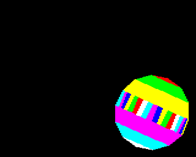
The first line of the program draws the scene ready for colour cycling. If we delete the rest of the program and just run line 1, we (eventually) get the following:
Note, this program requires the Graphics Extension ROM to draw the filled circle for the shadow
The background and shadow are solid colours and all the colours for the ball are all flashing. This means the logical colours for the ball use values 8-15.
Clearing the Screen
The first part of line 1, sets graphics mode 2 and clears the screen to cyan.
1 MODE 2:COLOUR 134:CLS
COLOUR sets the text colour. Values from 0-15 set the foreground colour and values from 128-143 set the background colour.
We are setting the colour to 134 which sets the background colour to cyan. We are then calling CLS to (CL)ear the (S)creen.
The next part draws a black circle for the shadow.
GCOL 0,0
Sets the graphics foreground colour to black.
MOVE 1029,250
Moves the graphics cursor to the centre of the circle we are going to draw (near the bottom right of the screen).
PLOT 153,250,0
draws a filled circle at the graphics cursor position with radius 250.

Drawing the Rest of the Ball…
The next part of the program draws the ball. This uses colours 8-15 for animation with colour cycling.
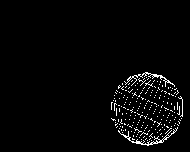
The ball is drawn in 7 slices from top to bottom. Illustrated here by drawing each slice with a different colour.

The J FOR loop iterates through the slices.
FOR J=0 TO 6
Each slice is drawn in segments from right to left. Here I’ve illustrated the segments by drawing each segment for the middle slice in a different colour.
The X FOR loop iterates through the segments.
FOR X=1 TO 19
When we calculate the position to draw each segment, we don’t want them to be evenly spaced. We want the distribution of the positions to look like they are points that are evenly distributed on a circle that are projected onto the X axis.
We use COS to do this. COS will turn a rotation angle around our circle to the projected X position from -1 to 1 that we want.
COS works in radians and there are 2 x PI radians in a full rotation. We only want to distribute our points over half a rotation so we want to evaluate values for COS in the range 0 to PI.
We are drawing each slice as a triangle strip. For each segment we visit in the slice we will PLOT two new points but they will have the same angle around the sphere so the COS value we want to calculate for both of these is the same. This means we can calculate the COS value at this point in the program and use it for both points we want to PLOT.
C=COS(X*PI/21)
We are calculating the angle to pass in to COS here as if our values for X go from 0 to 21. In fact they go from 1 to 19. We miss out some of the thinner segments at the edge as an optimization so the drawing finishes in time for the bot.
For each segment we visit a point on the current and next slice.
FOR K=J TO J+1
We then set the graphics colour for the triangles we will draw. This is explained further in the previous post on colour cycling grids.
We increase the colour by one with each segment. The segment index is in the FOR loop variable X
X
and for each slice (J) we add an offset of half the number of colours we will be colour cycling so that we see the grid pattern.
X + J*4
to simplify some of the program we are only going to colour cycle the colours from 8 to 15. First we will wrap values to keep them in a 0-7 range using MOD 8
(X + J*4) MOD 8
and then we will offset the values in the 0-7 range to be in the 8-15 range by adding 8
8 + (X + J*4) MOD 8
So our GCOL command ends up as:
GCOL 0,8+(X+J*4) MOD 8
The next section calculates the U and V which are the co-ordinates of the point on the sphere we are drawing before it is tilted.
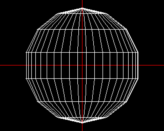
Before we do this, we calculate how far vertically down the sphere we are. Similarly to how we adjusted the horizontal position using COS, we do the same for the vertical position so that instead of the slices being evenly spaced like the diagram on the left, the slices at the top and bottom of the sphere are made thinner than the ones in the middle.
H=COS(K*PI/7)
H is now a value from -1 to 1 which represents the vertical position on the sphere.
We have our variable C which is a -1 to 1 value representing how far around the sphere we are for the segment we are on. If we just use C, each slice will be the same radius and we will draw a cylinder. To look like a sphere, we want to scale C by a factor depending on H. We can use Pythagoras’ theorem to calculate this scale factor.
a^2 = b^2 + c^2
Here a, the hypotenuse, is the radius of the circle. b is the vertical position on the circle and c is the horizontal position on the circle.
We can rearrange to get: c = sqrt( a^2 - b^2 )
And as we have a unit circle, our hypotenuse (the radius of the circle) is always 1.
c = sqrt( 1 - b^2 )
Calculating the scale factor U for a slice at height H.
In our program it looks like this. At this point the size of the sphere is also scaled up to have a radius of 25 units.
U=25*C*SQR(1-H*H)
The vertical co-ordinate V is simply set to the -1 to 1 H value also scaled up by the same factor of 25.
V=25*H
The next part of the program PLOTs the triangles.
PLOT 84-(X>1),990+U*9+V*4,290+V*9-U*4
There are a number of things going on here. The first argument to PLOT
84-(X>1)
is selecting between drawing a triangle and just moving the graphics cursor depending on whether we are at the start of a new slice.
The U and V we have calculated are co-ordinates of the sphere with radius 25 centred at the origin.
The second two arguments to the PLOT command are the screen co-ordinates to plot.
990+U*9+V*4,290+V*9-U*4
This is applying a 2D rotation, scale and translation to draw the sphere at the correct screen co-ordinates.
To rotate a co-ordinate, we want to take our (U,V) and move it to a new co-ordinate system. We can define the X and Y axes of our new co-ordinate system in terms of vectors in our old co-ordinate system.
To move one unit along our new X axis, drawn in red above we go in the direction ( cos(a), -sin(a) ). To move one unit along our new Y axis we go in the direction ( sin(a), cos(a) ).
To rotate our point with co-ordinate (U,V) by angle A about the origin, we go along the new X axis (red) by an amount U and add to that a movement along the new Y axis (green) by amount V.
Click on the various points to interact
(rotatedX, rotatedY) = ( cos(a) * U, -sin(a) * U ) + ( sin(a) * V, cos(a) * V )
To scale around the origin we can multiply a co-ordinate by the scale factor.
(scaledX, scaledY) = ( originalX * scale, originalY * scale )
We can combine the scale and rotation
(newX,newY) = ( cos(a)*scale*U, -sin(a)*scale*U ) + ( sin(a)*scale*V, cos(a)*scale*V )
or
newX =  cos(a) * scale * U  +  sin(a) * scale * V
newY = -sin(a) * scale * U  +  cos(a) * scale * V
As the sphere in this program is rotated and scaled by a fixed amount, ‘a’ and ‘scale’ are constants. We can calculate the sin() and cos() values of a and multiply them by scale. In this case I chose an angle and scale so I could round the result to single digits. The scale is approximately 10 and the angle is about 24 degrees or .42 radians.
sin( 0.42 ) * 10 = 4.07760
cos( 0.42 ) * 10 = 9.13089
I then ruthlessly rounded these to the nearest whole number so that they could be represented as a single digit, saving space in the program. This is where the 9s and 4s in the above line of program come from. This is also why the earlier scale factor of 25 was applied as doing the scale in these two places using whole numbers is overall a program length saving.
With our appoximations of sin(a) * scale being 4 and cos(a) * scale being 9 we can simplify:
newX =  cos(a) * scale * U  +  sin(a) * scale * V
newY = -sin(a) * scale * U  +  cos(a) * scale * V
to
newX =  9 * U  +  4 * V
newY = -4 * U  +  9 * V
Applying the translation is simple, we are just adding 990 to the X co-ordinate at 290 to the Y co-ordinate which will translate our co-ordinates to have a new origin at (990, 290).
newX = 990 +  9 * U  +  4 * V
newY = 290 + -4 * U  +  9 * V
which is how we get the X and Y co-ordinates for the PLOT statement we were looking at:
990+U*9+V*4,290+V*9-U*4
The next part of the program is just iterating the 3 FOR loops for rows, segments and slices
:NEXT,,
The last part of the first line is not part of drawing the scene but is actually part of…
Part 2 - Animation
The last statement of line one
V=1
sets up the X velocity of the ball, initially to be 1 so the ball starts off moving to the right.
The rest of the animation code continues from the next line, line… er… 5.
There are two sections to the animation code. The ball movement and the colour cycling to animate the ball rotation.
The ball movement uses a feature of the BBC Micro that lets us scroll the screen or rather, set where the start address of the screen memory will be. This is a little complicated and at certain boundary points parts of the screen will wrap around. In short this is why the ball is initally drawn in the bottom right corner, so we can move the screen start address and the blank areas at the top left will wrap around to the bottom and right.
To set the start address of screen memory we need to write to the 6845 cathode-ray tube controller address register. This is located at memory address &FE00.
We want to setup P so we can write to this address. We could do this by setting P=&FE00.
As this address is 512 bytes from the end of memory we can cheat to save some characters and achieve something similar with the next part of the program
P=-512
To make the ball bounce we figure out the position of the ball and translate this into the address we want screen memory to start from. J is the current frame of the vertical bounce animation. We are starting from whatever value we ended up with at the end of the J FOR loop in the drawing part of the program. The vertical bounce animation is 25 frames long and then repeats. We figure out ‘U’ the frame in the vertical bounce animation by taking ‘J’ modulo 25.
:U=J MOD25
X is the Ball X position which is also initially set to whatever X ended up being in the drawing loop. We add the current ball X velocity ‘V’ (which is -1 or 1) to the current X to update it.
:X=X+V
We then increment ‘J’, the vertical bounce animation frame number.
:J=J+1
We then caluclate ‘A’ which is where we want our screen address to start.
:A=&600+X+INT(U*2.5-U*U*.1)*80
The original screen address is &600 which is the base address we are adding other values to.
The MODE 2 screen memory layout constrains the resolution of the scrolling we can perform. We can only scroll horizontally in increments of two pixels and we can only scroll vertically in increments of one character (8 pixels).
We add the ball X position to the base address which will effectively offset the start address of the screen horizontally by X * 2 pixels.
The vertical bounce animation follows a parabola which we evaluate with a quadratic equation. This is the
(U*2.5-U*U*.1) term which we round to be an INTeger. We multiply this Y co-ordinate by 80 which moves us in increments of vertical lines of characters.
The final part of this line:
:IF X<3 OR X>44V=-V
makes the ball bounce off the side of the screen by negating the X velocity when the ball gets to a certain position.
line 6
6*FX19
Makes the program pause for a while and wait until the vertical blank to reduce tearing. This command needs to be the last thing on a line but we can’t move it to the line before as that is using an IF statement.
The first part of line 7 sets the screen start address.
We have effectively set P to &FE00 which is the address of the 6845 cathode-ray tube controller address register. Setting a value to this address, says which setting in the CRT controller we will be changing. Then setting a value in P+1 sets the value we want to set.
Setting P to 12 lets us set the high byte of the memory-address of the first screen-character (by then putting the value in P+1).
7?P=12:P?1=A/256
Setting P to 13 lets us set the low byte of the memory-address of first screen-character (by then putting the value in P+1).
:?P=13:P?1=A
We do not need to calulate A modulo 256 as this is done automatically when we use ? to write a value to a byte.
The next part of the program updates the palette to apply the colour cycling to animate the rotation of the ball. This is explained further in the previous posts with the additional change to affect which palette entries we change based on the direction the ball is spinning (based on the X velocity variable V).
:C=8+(X+V*2)MOD 8:VDU 19,C,1;0;19,8+(C+4)MOD 8,7;0;
The final part loops the animation
:GOTO 5
…
So that is the deconstruction of the program in my orignal tweet.
Steve McCrea (@Kweepa) has extended this and managed to squish down a single tweet version enough that it doesn’t need to use the Base2048 encoding!
— BBC Micro 🦉 Bot (@bbcmicrobot) July 25, 2020
And @rheolism took this even further.
— BBC Micro 🦉 Bot (@bbcmicrobot) October 28, 2020
Steve McCrea has also written another version (bigger than a tweet) that more closely resembles the original Amiga demo.
The Boing Ball in one screen of BBC BASIC. pic.twitter.com/DFBbCVUc1G
— Steve McCrea (@Kweepa) July 25, 2020